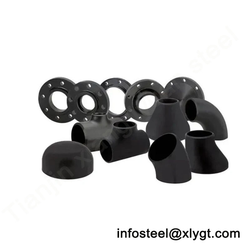
The Junction Points of Piping Systems
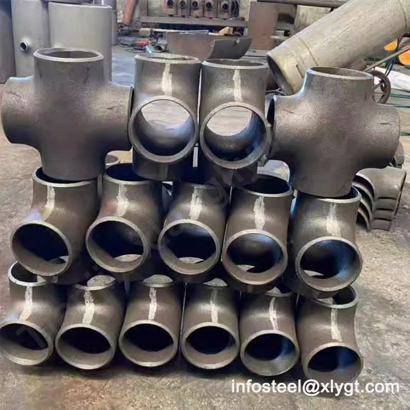
In the complex network of industrial piping, tees and crosses serve as the critical intersection points where flow distribution, direction alteration, and system branching occur. These essential fittings transform simple pipelines into functional systems capable of serving multiple processes, equipment, and destinations simultaneously. As specialized components that endure unique stress patterns and flow dynamics, their proper selection and specification directly impact system efficiency, maintenance accessibility, and operational safety.
At Tianjin Xiangliyuan Steel, we understand that the junction points of your piping system require engineering precision that matches or exceeds that of the straight pipe runs. This comprehensive technical guide provides detailed insights into tee and cross fittings, offering the specification knowledge necessary for optimal system design while demonstrating why our integrated approach to supplying both pipes and fittings delivers unmatched compatibility and performance reliability.
Technical Specifications and Standards Overview
Global Standards and Compliance
Pipe tees and crosses are manufactured according to internationally recognized standards that ensure dimensional consistency, pressure integrity, and material quality:
Primary Standards:
ASME B16.9: Factory-made wrought steel butt-welding fittings (most common for industrial applications)
ASME B16.11: Forged steel fittings, socket-welding and threaded
MSS SP-75: Specifications for high-test, wrought butt-welding fittings
ISO 4144: Stainless steel pipeline components
EN 10253-2: Butt-welding pipe fittings for general purposes
GB/T 12459: Chinese national standard for steel butt-welding pipe fittings
Pressure Classifications:
Standard pressure classes: 150#, 300#, 600#, 900#, 1500#, 2500#
Special classes for specific applications (nuclear, subsea, etc.)
Pressure-temperature ratings governed by ASME B16.34
Dimensional Tolerances:
Outside diameter: ±0.5% to 1% depending on size
Wall thickness: Minimum 87.5% of nominal thickness
Center-to-end dimensions: ±1.5mm for sizes up to NPS 24″
Alignment: Run-out tolerance typically 1/16″ per inch of fitting length
Pipe Tees – Types, Specifications, and Applications
2.1 Equal Tee (Straight Tee)
Definition and Geometry:
An equal tee features three openings of identical diameter, with the branch connection positioned at a 90° angle to the main run. The internal intersection is carefully contoured to minimize turbulence and pressure drop.
Technical Specifications:
Size Range: NPS ½” to 48″ (DN 15 to DN 1200)
Angles: Standard 90° branch; 45° lateral tees available for special applications
Materials:
Carbon Steel: ASTM A234 WPB (standard), WPC, WP1, WP12
Stainless Steel: ASTM A403 WP304/304L, WP316/316L, WP321
Alloy Steel: ASTM A234 WP5, WP9, WP11, WP22, WP91
Low Temperature: ASTM A420 WPL6, WPL3
Manufacturing Methods: Hot forming, cold forming, or fabricated from pipe and plate
Flow Characteristics:
Flow area ratio: Approximately 1:1:1 (run:run:branch)
Pressure drop coefficient (K-factor): 0.8-1.2 depending on flow direction
Stress intensification factor: 2.1-2.5 per ASME B31.3
Primary Applications:
General process piping branching
Instrument tap connections
Utility distribution systems
Fire protection sprinkler systems
Equal distribution points in parallel systems
Procurement Considerations:
When ordering equal tees, specify if special end preparations are required (bevel type, land dimensions). For services with potential erosion, consider ordering with additional reinforcement at the branch intersection. Verify that the fitting schedule matches the connecting pipe schedule to ensure proper pressure rating continuity.
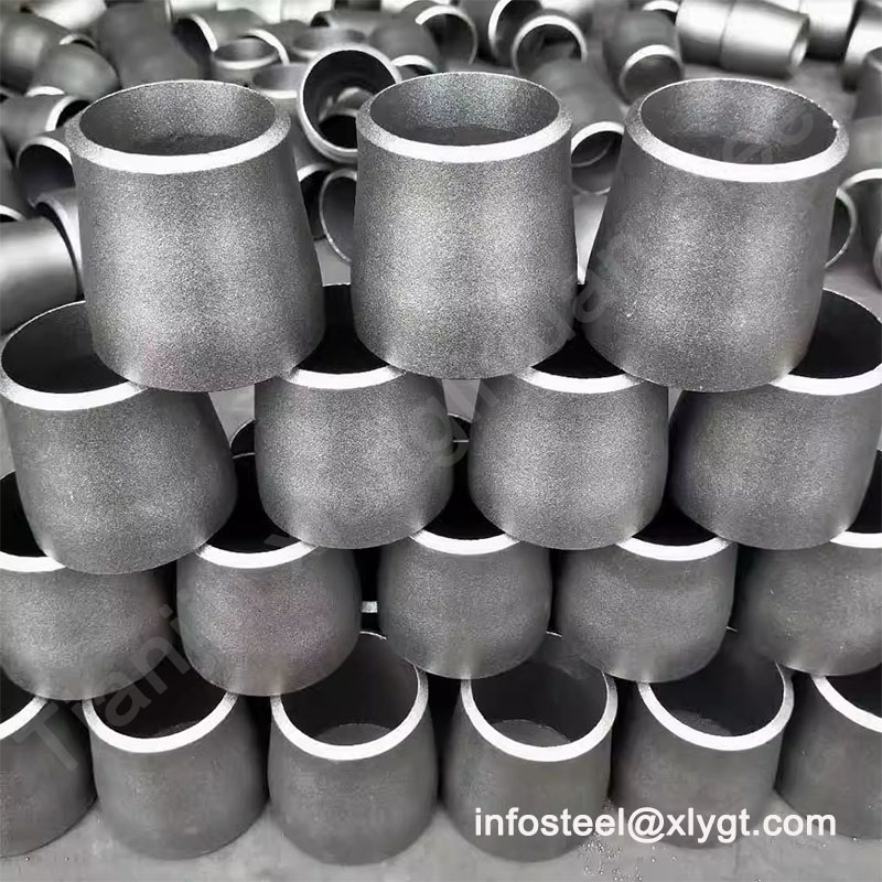
2.2 Reducing Tee (Unequal Tee)
Definition and Geometry:
A reducing tee features a branch connection of smaller diameter than the main run, allowing for take-off connections to smaller piping without additional reducers.
Technical Specifications:
Size Combinations: All standard pipe size reductions (e.g., 8″ x 8″ x 6″, 6″ x 6″ x 4″)
Branch Types:
Straight Branch: Standard 90° connection
Lateral Branch: 45° connection for reduced turbulence
Reinforcement Requirements:
Area replacement calculations per ASME B31.3
Reinforcement pads or integrally reinforced designs for high-pressure applications
Materials and Grades:
Same material availability as equal tees, with careful attention to weldability between different wall thicknesses when significant size reduction occurs.
Flow Dynamics:
Flow area mismatch creates localized turbulence
Velocity increase through smaller branch creates Venturi effect
Pressure recovery characteristics vary with flow ratio
Primary Applications:
Pump suction and discharge headers
Compressor station piping
Heat exchanger connections
Control valve bypass arrangements
Sampling system connections
Special Design Considerations:
Extruded Outlet Tees: Feature a smooth, gradual transition from run to branch, reducing stress concentration
Swage Tees: Incorporate both reducing tee and swage nipple functions
Reinforced Tees: Include integral reinforcement at branch junction for high-pressure services
Procurement Specifications:
When ordering reducing tees, clearly specify all three dimensions in order: Run x Run x Branch (e.g., 10″ x 10″ x 8″). Indicate if special reinforcement is required based on your design calculations. For services with significant thermal cycling, consider specifying normalized or stress-relieved fittings.
2.3 Special Tee Configurations
Barred Tee:
Features internal bars across the branch outlet
Prevents pigging tools from entering branch lines during pipeline cleaning
Common in transmission pipelines with maintenance pigging requirements
Bars designed to minimize flow restriction while containing pigs
Scraper Tee:
Similar to barred tee but with specific geometry for scraper passage
Includes guide bars and radiused transitions
Used in pipelines requiring regular internal inspection or cleaning
Hydraulic Tee (Diffuser Tee):
Features internal flow distribution vanes or diffusers
Minimizes turbulence when combining flows
Used in hydraulic systems and parallel pump arrangements
Sanitary Tee:
Polished internal surfaces (typically Ra ≤ 0.8μm)
Radiused corners for cleanability
Compliant with 3-A, FDA, or EHEDG standards
Common in food, pharmaceutical, and bioprocessing industries
Pipe Crosses – Specifications and Applications
3.1 Equal Cross (Straight Cross)
Definition and Geometry:
A pipe cross features four openings of equal diameter arranged at 90° intervals, creating two intersecting flow paths perpendicular to each other.
Technical Specifications:
Size Range: Typically NPS ½” to 12″ (DN 15 to DN 300) for standard manufactured crosses
Larger Sizes: Usually fabricated from pipe and plate rather than formed
Materials: Similar to tees but with more restrictive size/material combinations due to manufacturing complexity
Stress Considerations:
High Stress Concentration: The intersection of four pipes creates complex stress patterns
Stress Intensification Factors: Typically 2.5-3.5 times straight pipe
Thermal Stress: Significant constraint against thermal expansion in multiple directions
Manufacturing Methods:
Hot Formed: Press formed from solid billet or pipe (smaller sizes)
Fabricated: Welded construction from pipe segments and plate (larger sizes)
Forged: For high-pressure applications in smaller sizes
Limited Applications Due to:
High stress concentration at intersection
Complex fabrication requirements
Significant pressure drop when flow passes through
Difficult reinforcement design
Primary Applications:
Fire protection sprinkler systems (distribution to multiple zones)
Certain chemical processes requiring simultaneous distribution
Air distribution in HVAC systems
Cooling water distribution networks
Alternative Solutions:
In most industrial applications, engineers prefer using two tees spaced apart rather than a single cross to reduce stress concentration and simplify reinforcement design.
3.2 Reducing Cross
Definition and Geometry:
A reducing cross features different diameters on one or more openings, allowing complex distribution patterns in a single fitting.
Technical Specifications:
Even more restricted availability than equal crosses
Typically custom-fabricated rather than standard stock items
Requires detailed engineering design and stress analysis
Procurement Considerations:
Reducing crosses are generally special-order items requiring:
Complete dimensional drawings
Material specifications for each connection
Pressure-temperature design conditions
Reinforcement design calculations
Non-destructive examination requirements
Material Selection and Technical Considerations
4.1 Material Compatibility and Specifications
Carbon Steel Tees/Crosses (ASTM A234):
WPB: Most common grade for general service (-20°F to 800°F)
WPC: Improved notch toughness for moderate low-temperature service
WP1/WP12/WP11/WP22: Increasing alloy content for elevated temperature service
WP5/WP9/WP91: High chromium-molybdenum alloys for severe temperature/pressure conditions
Stainless Steel Tees/Crosses (ASTM A403):
WP304/304L: General corrosion resistance, widely available
WP316/316L: Enhanced chloride resistance, common in chemical processing
WP321/347: Stabilized grades for high-temperature service
WP309/310: High-temperature oxidation resistance
Special Alloys:
Duplex Stainless Steels: UNS S31803/S32205 for chloride environments
Nickel Alloys: Inconel, Monel, Hastelloy for severe corrosion conditions
Clad/Lined Fittings: Carbon steel with stainless or alloy liner for cost optimization
4.2 Reinforcement and Stress Management
Branch Reinforcement Requirements:
Area Replacement Method: ASME B31.3 requires replacement of metal removed for branch connection
Reinforcement Options:
Integral Reinforcement: Additional material forged or formed at branch junction
Reinforcement Pads: Separate annular rings welded around branch connection
Saddle Reinforcement: Partial reinforcement for specific applications
Stress Analysis Considerations:
Finite Element Analysis (FEA) recommended for critical service fittings
Consider both pressure stress and thermal expansion stress
Account for external loads (valves, equipment, supporting structures)
Fatigue analysis for cyclic service conditions
4.3 Flow Dynamics and Pressure Drop
Tee Flow Patterns:
Combining Flow: Two streams merging into one (highest turbulence)
Dividing Flow: One stream splitting into two (moderate turbulence)
Straight-Through Flow: Minimal disturbance when branch is closed
Pressure Drop Coefficients:
Vary significantly with flow ratio and direction
Published K-values available in hydraulic handbooks
CFD analysis recommended for critical flow applications
Erosion Considerations:
Maximum velocity limits based on fluid properties
Material selection for abrasive services
Potential need for wear pads or special alloys in erosion zones
Quality Assurance and Inspection
5.1 Manufacturing Process Control at Tianjin Xiangliyuan Steel
Material Verification:
Mill Test Certificate review and verification
Positive Material Identification (PMI) using XRF analyzers
Chemical composition validation against specification requirements
Dimensional Inspection:
100% verification of critical dimensions
Wall thickness measurement using ultrasonic thickness gauges
Bevel angle and land dimension confirmation
Roundness and straightness verification
Non-Destructive Examination:
Visual Inspection: All fittings examined for surface defects
Dye Penetrant Testing: For surface-breaking defects on critical fittings
Magnetic Particle Testing: For ferromagnetic materials
Ultrasonic Testing: For internal defects and thickness verification
Radiographic Testing: For fabricated tees/crosses as specified
Certification and Traceability:
Unique heat number tracking throughout manufacturing
Complete documentation package with each shipment
Compliance certificates for specified standards
Material test reports with actual values
Procurement Guidelines and Best Practices
6.1 Specification Checklist for Tees and Crosses
Essential Information to Provide:
Type and Configuration: Equal tee, reducing tee, barred tee, cross, etc.
Nominal Size(s): For reducing fittings, specify all dimensions
Schedule/Wall Thickness: Match connecting pipe or specify minimum
Material Specification: ASTM standard and grade
Pressure Class: 150#, 300#, etc., or specific design pressure
End Connections: Butt-weld, socket weld, threaded, or special
Reinforcement Requirements: Integral, pad, or special reinforcement
Special Features: Barred, sanitary finish, special coatings, etc.
Testing Requirements: Non-destructive examination specifications
Certification Requirements: Material, dimensional, pressure testing
6.2 Common Specification Errors to Avoid
Schedule Mismatch: Ordering fittings with different schedule than connecting pipes
Material Incompatibility: Specifying fittings with different material grade than pipes
Insufficient Reinforcement: Not accounting for branch reinforcement requirements
Wrong End Preparation: Specifying incorrect bevel angles or land dimensions
Overspecifying Crosses: Using crosses where tee pairs would be more appropriate
6.3 Value-Added Services from Tianjin Xiangliyuan Steel
Technical Support:
Application engineering assistance
Material selection guidance
Reinforcement design consultation
Stress analysis recommendations
Custom Manufacturing:
Special sizes outside standard ranges
Unique configurations for specific applications
Special material combinations
Integrated reinforcement designs
Quality Documentation:
Complete traceability documentation
Third-party inspection coordination
Special certification requirements fulfillment
Digital documentation packages
Optimizing Your Piping System Junctions
The selection of appropriate tee and cross fittings represents a critical engineering decision that balances flow requirements, stress management, maintenance considerations, and economic factors. From the straightforward distribution of equal tees to the specialized configurations of barred or extruded outlet designs, each fitting type serves specific purposes within well-designed piping systems.
At Tianjin Xiangliyuan Steel, our expertise extends beyond manufacturing to encompass comprehensive understanding of how these junction fittings perform within complete piping networks. We recognize that tees and crosses represent points of potential vulnerability that require superior engineering, precise manufacturing, and rigorous quality assurance.
When you choose Tianjin Xiangliyuan Steel as your source for pipe fittings, you benefit from:
Vertical Integration: Seamless compatibility between our pipes and fittings
Technical Depth: Engineering support based on decades of application experience
Quality Commitment: Stringent inspection protocols ensuring reliability
Supply Chain Efficiency: Consolidated procurement for pipes and fittings
Global Standards Compliance: Products meeting international specifications
For complex piping systems where junction integrity is paramount, our technical team provides specification guidance, material selection advice, and custom manufacturing solutions. We invite you to contact us at infosteel@xlygt.com to discuss your specific tee and cross requirements, request detailed quotations, or access our comprehensive technical documentation.
Let Tianjin Xiangliyuan Steel be your trusted partner in creating piping systems where every junction—like every straight run—delivers uncompromising performance and reliability. Our commitment to engineering excellence ensures that the intersection points of your systems become strengths rather than vulnerabilities.