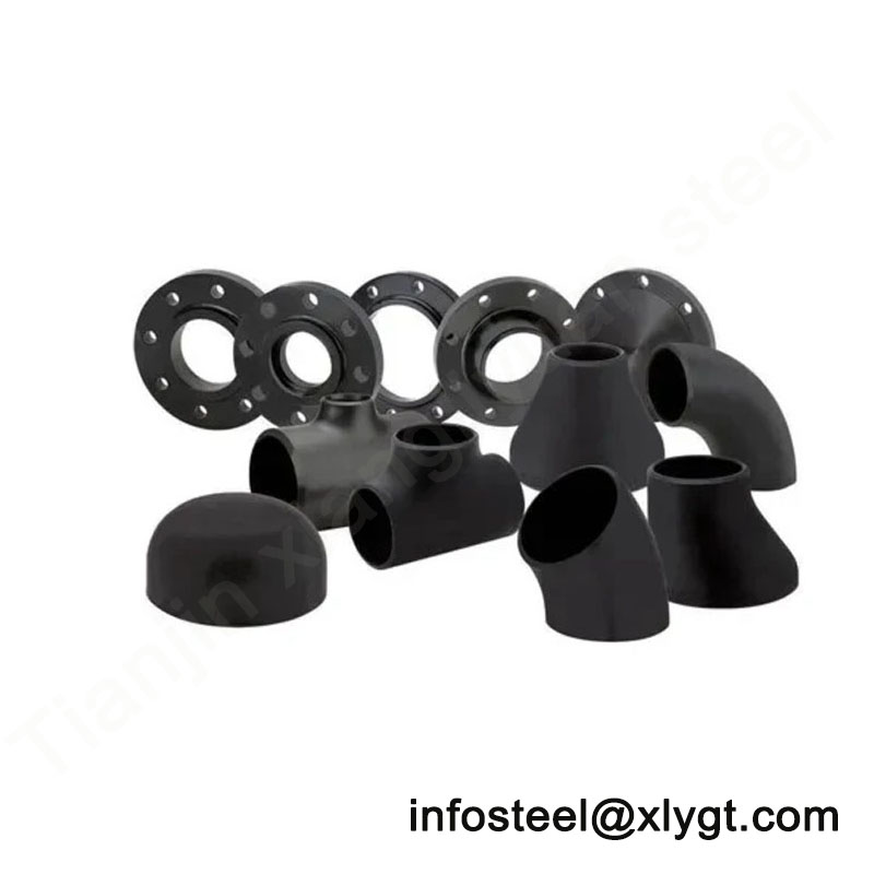
Mastering Flow Transition in Piping Systems
In the engineered world of industrial piping, the management of flow velocity, pressure, and phase distribution often necessitates precise changes in pipeline diameter. Pipe reducers, commonly referred to as reducing fittings or “bull plugs,” serve as the critical transition components that facilitate these diameter changes in a controlled, efficient, and reliable manner. Far from being simple connectors, reducers are hydrodynamic devices that significantly influence system pressure drop, flow regime stability, erosion potential, and operational safety.
At Tianjin Xiangliyuan Steel, we approach reducer manufacturing with the understanding that these fittings represent calculated points of energy transformation within a piping system. This exhaustive technical guide delves into the engineering principles, specification parameters, and application-specific considerations for both concentric and eccentric reducers. Our aim is to equip you with the knowledge to specify optimal reducer solutions while highlighting the integrated expertise we offer as a premier supplier of both precision steel pipes and their perfectly matched fittings.
Fundamental Classifications and Operating Principles
1.1 Concentric Reducers
Definition and Geometric Configuration:
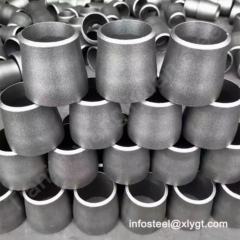
A concentric reducer is characterized by a symmetrical, conical transition section that maintains a common centerline between the larger and smaller diameter ends. This axisymmetric design ensures uniform flow constriction or expansion around the entire pipe circumference.
Key Standards and Dimensional Specifications:
Primary Standards: ASME B16.9 (factory-made wrought butt-welding), ASME B16.11 (forged/socket weld), MSS SP-75, EN 10253-2, GB/T 12459
Pressure Classes: 150#, 300#, 600#, 900#, 1500#, 2500# (aligned with connecting pipe ratings)
Size Range: From NPS ½” x ¼” up to NPS 48″ x 42″ and larger for custom fabrications
Reduction Ratios: Typically limited to 2-3 pipe size reductions per fitting (e.g., 8″ to 6″); larger reductions may require multiple reducers in series
Included Angle: Standard taper angles range from 10° to 45°; optimal hydraulic design typically employs 15°-25° for minimal pressure loss
Materials and Grades:
Carbon Steel: ASTM A234 WPB (standard service), WPC, WP1, WP12, WP11, WP22
Stainless Steel: ASTM A403 WP304/304L, WP316/316L, WP321, WP347
Alloy Steel: ASTM A234 WP5, WP9, WP91 (high-temperature applications)
Low-Temperature Steel: ASTM A420 WPL6, WPL3
Special Alloys: Duplex (S31803/S32205), Nickel Alloys (Inconel, Monel)
Flow Dynamics and Pressure Drop Characteristics:
Sudden vs. Gradual Transition: Concentric reducers provide a controlled, gradual area change versus an abrupt orifice-like transition
Pressure Recovery: The conical design allows for partial pressure recovery downstream, reducing permanent pressure loss
Coefficient of Resistance (K-factor): Ranges from 0.05 (for very gradual 10° reducers) to 0.45 (for sharp 45° reducers) based on Crane Technical Paper 410
Velocity Profile Distortion: Minimal disruption to established flow profiles when properly sized
Primary Applications and Industry Usage:
Pump Discharge Lines: Gradually increasing velocity to match downstream piping
Flow Metering Runs: Creating stabilized flow conditions upstream of measurement devices
Compressor Station Piping: Managing gas velocity changes in transmission systems
Process Reactors: Controlling residence time through velocity adjustment
Heat Exchanger Piping: Matching nozzle connections to main piping
Critical Procurement Considerations:
Always specify both end diameters in order: Large End x Small End (e.g., 10″ x 8″)
Verify that the reducer schedule matches the thicker of the two connecting pipes
For pump suction applications, concentric reducers are generally not recommended due to potential vapor pocket formation
Consider multi-stage reducers for large diameter reductions (>3 pipe sizes) to avoid excessive pressure drop
1.2 Eccentric Reducers
Definition and Geometric Configuration:
An eccentric reducer features an offset centerline, creating a gradual transition that is flat on one side. This design maintains either the top or bottom of pipe elevation across the diameter change, a critical feature for liquid drainage or vapor venting.
Orientation Specifications:
FBO (Flat Bottom – Eccentric Reduction Downward): Maintains constant bottom-of-pipe elevation; most common orientation
FTO (Flat Top – Eccentric Reduction Upward): Maintains constant top-of-pipe elevation; used in specific applications
Key Standards and Dimensions:
Complies with same dimensional standards as concentric reducers (ASME B16.9, etc.)
Offset distance equals half the difference between large and small diameters
Available in same material grades and pressure classes as concentric types
Hydraulic Characteristics:
Asymmetric Flow Transition: Creates complex, three-dimensional flow patterns with secondary currents
Phase Separation Management: Intentionally prevents liquid accumulation in gas lines or vapor pockets in liquid lines
Minimal Solids Deposition: Flat side prevents settling of particulates during low-flow conditions
Primary Applications and Industry Usage:
Pump Suction Piping (Critical Application): FBO orientation prevents vapor accumulation and cavitation
Horizontal Process Lines: Maintaining drainable profiles in slurry or viscous fluid services
Gas Transmission Pipelines: Preventing liquid accumulation at low points
Steam Distribution Systems: Ensuring condensate drainage toward drip legs
Wastewater and Slurry Lines: Minimizing solids deposition during velocity changes
Critical Procurement Considerations:
Must specify orientation: FBO (Flat Bottom) or FTO (Flat Top) – this is not optional
Installation direction is critical – arrow marking indicating flow direction is essential
For pump suction: Reducer should be installed directly at pump flange with FBO orientation
Consider vortex formation in FTO configurations with low liquid levels
Specialized Reducer Types and Configurations
2.1 Swage Nipples (Swage Reducers)
Definition and Configuration:
Short-length, threaded or socket weld reducers typically used for connecting pipes to smaller threaded equipment connections or instrument taps.
Technical Specifications:
Standards: ASME B16.11 (forged steel), ASTM A105/A182 materials
Types: Concentric and eccentric designs available
End Configurations: Threaded x Threaded, Threaded x Socket Weld, Socket Weld x Socket Weld
Size Range: Typically NPS ½” to 4″ with reductions to ¼” or smaller
Applications:
Instrument connections (pressure gauges, transmitters)
Small valve connections
Sample point installations
Chemical injection points
2.2 Multi-Stage Reducers
Design Principle:
For large diameter reductions (>4 pipe sizes), a single reducer with extreme taper angle creates excessive turbulence and pressure drop. Multi-stage configurations use two or more reducers in series with intermediate pipe spools.
Engineering Guidelines:
Maximum recommended reduction per stage: 2 pipe sizes
Intermediate spool length: 3-5 pipe diameters for flow re-establishment
Taper angle per stage: 15°-20° optimal
Tianjin Xiangliyuan Steel can supply pre-fabricated reducer assemblies with intermediate spools
2.3 Internally Lined/Coated Reducers
Specialized Construction:
For corrosive or abrasive services, reducers may be manufactured with:
Bimetal Construction: Carbon steel outer with stainless or alloy liner
Plastic/Rubber Lining: Full bore lining for chemical resistance
Ceramic Coating: For extreme erosion resistance in slurry applications
Engineering Design and Selection Methodology
3.1 Hydraulic Design Considerations
Pressure Drop Calculations:
The pressure loss through a reducer is calculated using:
Darcy-Weisbach Equation: ΔP = K × (ρ × v²/2)
Resistance Coefficient (K): Function of diameter ratio (d/D) and taper angle (θ)
Crane Method: K = 0.8 × sin(θ/2) × (1 – β²) for sudden expansion (β = d/D)
Idelchik Method: More comprehensive including Reynolds number effects
Velocity Change Implications:
Bernoulli Principle: Velocity increase (reduction) results in pressure decrease
Cavitation Risk: Liquid services approaching vapor pressure require careful analysis
Erosion Potential: Velocity thresholds for sand-bearing fluids (API RP 14E guidelines)
Flow Regime Preservation:
Laminar to turbulent transition considerations
Separation bubble formation in diffusing (expanding) flows
Swirl generation in eccentric reducers
3.2 Mechanical Design and Stress Analysis
Wall Thickness Transition:
ASME B31.3 Requirement: Minimum thickness at any point must satisfy pressure design formula
Transition Length: Typically 3-5 times the diameter difference
Corrosion Allowance: Must be maintained through tapered section
Stress Intensification:
Stress intensification factors (i-factors) lower than tees or elbows
Finite Element Analysis (FEA) for severe cyclic service
Thermal stress consideration due to varying thickness
Support and Alignment:
Concentric reducers generally don’t require special support
Eccentric reducers may create moment loads requiring consideration
Proper alignment critical during installation
3.3 Material Selection Guidelines
Service Condition Matrix:
| Service Condition | Recommended Material | Special Considerations |
|---|---|---|
| General Water/Oil/Gas | A234 WPB | Standard corrosion allowance |
| High Temperature (>800°F/427°C) | A234 WP11/WP22/WP91 | Creep strength, oxidation resistance |
| Cryogenic Service | A420 WPL6 | Impact testing at design temperature |
| Chloride Service | A403 WP316L | Stress corrosion cracking prevention |
| Sour Service (H₂S) | A105 with hardness control | NACE MR0175/ISO 15156 compliance |
| Abrasive Slurry | A234 WPB with wear plate | Localized reinforcement option |
Manufacturing Processes and Quality Assurance
4.1 Manufacturing Techniques at Tianjin Xiangliyuan Steel
Hot Forming Process:
Pipe Reduction Method: Heating and swaging pipe ends for smaller reducers
Plate Forming Method: Cutting and rolling tapered sections from plate, then welding seam
Forging Method: For high-pressure, small-size reducers (ASME B16.11)
Quality Control Protocols:
Material Certification: Full traceability from raw material to finished product
Dimensional Verification: 100% checking of ID/OD, wall thickness, taper angle, and length
Wall Thickness Mapping: Ultrasonic testing at multiple points, especially critical in tapered sections
Taper Angle Precision: ±1° tolerance on included angle
Surface Finish: Internal surface smoothness critical for flow efficiency
Specialized Testing:
Dye Penetrant Inspection: For all weld seams on fabricated reducers
Radiographic Testing: For critical service applications
Positive Material Identification: XRF verification of alloy composition
Pressure Testing: Hydrostatic testing to 1.5x design pressure available upon request
4.2 Marking and Documentation
Standard Marking (per ASME B16.9):
Manufacturer’s name or trademark (Tianjin Xiangliyuan Steel)
Material grade (ASTM specification)
Size (large end x small end)
Schedule or wall thickness
Heat number for traceability
For eccentric reducers: Clear “TOP” or “BOTTOM” marking
Documentation Package:
Certified Mill Test Reports (CMTR)
Material Chemical and Mechanical Certificates
Non-Destructive Examination Reports (if specified)
Certificate of Compliance with specified standards
Dimensions-as-built report for critical applications
Application-Specific Guidelines and Best Practices
5.1 Pump Piping Applications
Suction Reducer Guidelines (Critical):
Always use eccentric reducers with FBO (flat bottom) orientation
Install directly at pump suction flange (no straight pipe between)
For top suction pumps, special orientation may be required
Minimum straight pipe after reducer: 5-10 diameters before pump (except when reducer is at flange)
Discharge Reducer Guidelines:
Concentric reducers typically used
Locate after check valve, not between pump and check valve
Consider supporting weight of larger pipe section
5.2 Vertical Pipe Applications
General Rule:
Concentric reducers only in vertical lines
Eccentric reducers create unnecessary asymmetry in vertical flow
Supports must accommodate weight of larger diameter section above reducer
Downward Flow Considerations:
Potential for flow separation in expanding sections
Gas entrainment in liquid services
5.3 Two-Phase Flow Applications
Gas-Liquid Flow:
Eccentric reducers with proper orientation to prevent liquid accumulation
Velocity changes may alter flow regime (slug to annular, etc.)
Consider erosion at impingement points
Liquid-Solid Flow (Slurry):
Maintain minimum velocity to prevent settling
Eccentric FBO orientation to prevent solids accumulation
Consider wear-resistant materials or linings
Procurement Specification and Technical Queries
6.1 Comprehensive Specification Checklist
Mandatory Information for Quotations:
Type: Concentric or Eccentric (if eccentric, specify FBO or FTO)
Dimensions: Large End NPS x Small End NPS (e.g., 12″ x 8″)
Wall Thickness: Schedule number or minimum wall thickness
Material Specification: ASTM designation and grade
Design Conditions: Pressure, Temperature, and Corrosion Allowance
End Preparation: Bevel type (plain, compound), land dimensions
Special Requirements: Lining, coating, special testing, documentation
Applicable Standards: ASME B16.9, MSS SP-75, etc.
Quantity and Delivery Requirements
6.2 Common Specification Errors to Avoid
Orientation Omission: For eccentric reducers, failing to specify FBO/FTO
Schedule Mismatch: Specifying reducer schedule that doesn’t match connecting pipes
Excessive Reduction: Requesting single reducer for >3 pipe size reduction
Material Incompatibility: Different materials for reducer and connecting pipes without weld procedure
Wrong Application: Using concentric reducer on pump suction lines
Engineering Excellence in Flow Transition Management
The selection and specification of pipe reducers represent a critical intersection of hydraulic engineering, mechanical design, and practical installation considerations. Whether managing the cavitation risk in a pump suction line with an eccentric reducer or optimizing pressure recovery in a process line with a gradual concentric reducer, these fittings perform essential functions that directly impact system efficiency, reliability, and safety.
At Tianjin Xiangliyuan Steel, our engineering approach to reducer manufacturing extends beyond dimensional compliance to encompass comprehensive understanding of their performance within complete fluid systems. We recognize that a reducer is not merely a transition piece but a hydrodynamic device that requires precise geometry, material integrity, and manufacturing consistency.
When you partner with Tianjin Xiangliyuan Steel for your reducer requirements, you gain access to:
Integrated System Perspective: Understanding of how reducers interact with pumps, control valves, and other system components
Manufacturing Precision: Advanced forming and welding techniques ensuring dimensional accuracy and metallurgical integrity
Material Expertise: Correct grade selection for temperature, pressure, and corrosion requirements
Technical Validation: Engineering support for proper application and specification
Quality Certainty: Rigorous inspection protocols from raw material to finished product
For challenging applications involving two-phase flow, abrasive services, severe temperature gradients, or complex piping configurations, our technical team provides specialized guidance to ensure optimal reducer selection and performance.
We invite you to submit your reducer requirements, including challenging specifications and custom designs, to infosteel@xlygt.com for detailed technical evaluation and competitive quotation. Our engineering team is prepared to collaborate on optimizing your piping transitions for maximum efficiency and reliability.
Let Tianjin Xiangliyuan Steel be your single-source solution for integrated piping systems, where every component—from straight pipe to precisely engineered reducers—delivers uncompromising performance backed by technical excellence and quality assurance.